
The camshaft is a vital component of the Perkins 2506-15 industrial engine, responsible for controlling the opening and closing of the engine’s valves. If you need to replace or inspect the camshaft, this step-by-step guide will assist you in safely removing it. Remember to exercise caution during the removal process to avoid damage to the camshaft and its bearings.
Preparations:
Perkins EST 2023A & 2022A & 2019A Software Free Download
Perkins Communication Adapter 3
Procedures:
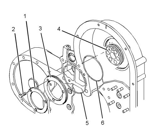
Step 1: Removing the Thrust Plate and Sealing Plate
1. Locate and remove the bolts securing the thrust plate (1) in place.
2. Proceed to remove the sealing plate (3) from the front housing, ensuring not to damage any surfaces.
3. Remove the adapter assembly (4) from the camshaft.
4. Take out the O-ring seals (5) and (6) from the sealing plate (3).
Note: It is crucial to handle the camshaft with care to prevent any damage to its finished surfaces and the camshaft bearings.
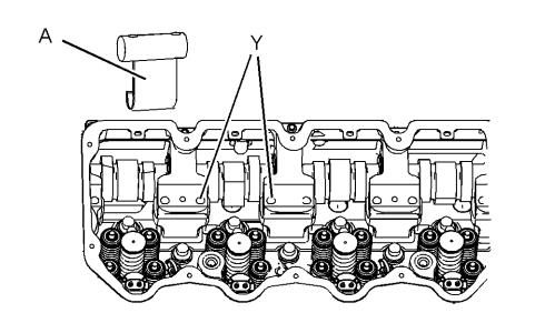
Step 2: Installing Tooling (A) and (B)
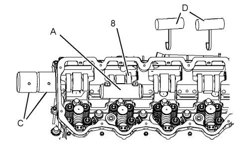
5. Utilize the bolts for the rocker arm shaft assembly to attach Tooling (A) at Location (Y).
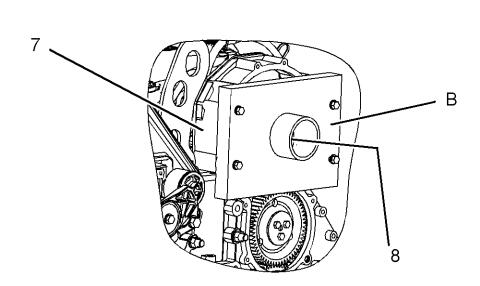
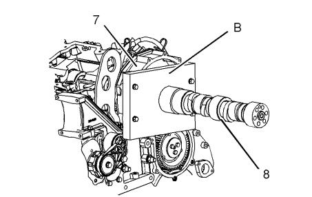
6. Install Tooling (B) onto the front housing (7) to support the camshaft (8). Avoid tightening the bolts for Tooling (B) at this stage.
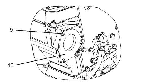
Step 3: Removing the Cover and O-ring Seal
7. Remove the Torx screws (9) securing the cover (10) and remove the O-ring seal from the cover.
Step 4: Preparing for Camshaft Removal
8. Shift the camshaft (8) forward and install one Tooling (C) on the end of the camshaft.
9. Move the camshaft further forward, placing the remaining Tooling (C) behind the first one. Align the camshaft (8) with the bore of Tooling (B). Tighten the bolts holding Tooling (B) to the front housing (7).
Note: Tooling (C) will support the rear of the camshaft during removal, preventing any misalignment that could damage the camshaft bearings.
Step 5: Removing the Camshaft
10. Using Tooling (D), carefully move the camshaft (8) towards the front of the engine. Adjust Tooling (D) as required.
Note: Avoid lifting the camshaft with Tooling (D). The camshaft should rest on Tooling (A). Lifting it could cause misalignment and damage the camshaft bearings.
11. Slide the camshaft to the front of the engine for removal, ensuring it remains level throughout the process. It is recommended to have two people for this task, considering the approximate weight of the camshaft (39 kg or 86 lb).
Note: Rotate the camshaft while removing it to prevent binding in the camshaft bearings.
Step 6: Completing the Removal Process
12. Remove Tooling (C) from the camshaft.
13. Remove Tooling (B) from the front housing (7).
14. Finally, remove Tooling (A) from the cylinder head.
More trouble repair case for Perkins,pls refer to:Perkins Trouble Repair