
Volvo Excavator Engine Body Instructions, Basic Inspection and Troubleshooting Instructions
VOLVO VCADS & VOLVO Diagnostic Tool for truck/ bus 2.40 Version
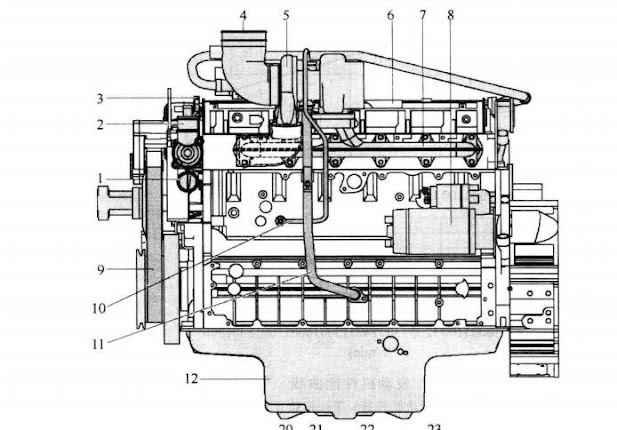
(1) Engine description The engine is 6-cylinder, 4-stroke, direct injection, turbocharged, aftercooled and has a cast iron block and cylinder head.
Volvo Tech Tool Diagnostic Software Training
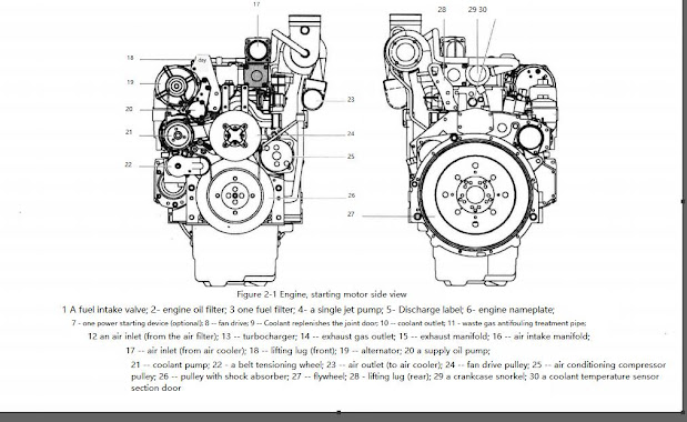
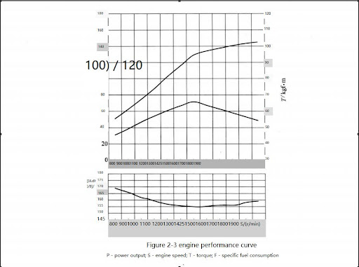
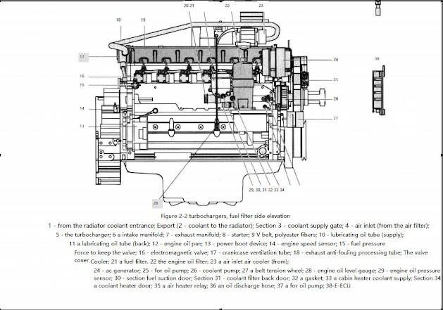
The gears in the engine gearbox are hardened helical type for strength and noise reduction, arranged in a way to provide quiet and smooth power transmission. Both the cylinder block and the cylinder head are designed with internal passages, which constitute the secret channel for lubricating oil and coolant. taut. The fan belt is a polyester V-belt for improved performance and is held in place by an automatic tensioner Figure 2-1 and Figure 2-2 are side views of the engine. Figure 2-3 is the performance curve of the engine.
VOLVO 88890300 Vocom Interface for VOLVO/Renault/UD/Mack Truck Diagnose
(2) Instructions for troubleshooting When a malfunction is suspected or confirmed, it is important to find the cause as quickly as possible. The starting point for all troubleshooting is that there is some symptom or malfunction. Faults can be indicated by: An error code is generated, a malfunction is detected.
① Troubleshooting operation The first step of troubleshooting is to collect information about the fault performance from the operator, and then try to determine the cause by checking in a certain order. The different inspection steps are as follows: Check error codes, check parameters, perform basic checks.
② Troubleshooting information a. Troubleshooting strategy Describe troubleshooting actions step by step. b. Auxiliary equipment for troubleshooting Briefly describe the auxiliary equipment that can be used for troubleshooting. c. Functional inspection and testing using testing equipment VCADS Pro. d. Error code information Contains error code design information, a list of all error codes, and error code information for each error code. e. Components, Troubleshooting, and Specifications Contains troubleshooting methods and numerical measurements of components. Also contains wiring diagrams and some specifications. f. Parameters Wrongly set parameters will cause malfunctions. The parameter list includes all limits and target values of the parameters. connect. g. Control device function description Describe the function, input and output of the control device and the communication between each control device h. Control device, active and passive measurements Contains the measured values of the active and passive measurements of ACAS. i. Software Functions Describe the prerequisites for the software in ACAS to perform control and monitoring functions.
(3) Basic inspection of the engine Certain tests and inspections are performed with the safety lock lever unlocked. Make sure that the machine cannot be operated accidentally with the safety lock lever unlocked. The purpose of the basic inspection is to provide quick and accurate information about the general condition of the engine. Basic checks should be carried out and evaluated following the guidance in the PC-tool VCADS Pro. The basic inspection divided into the following test items should be performed after reading the fault code and checking the parameters. The test is as follows.
① Cylinder compression test The purpose of this test is to show whether there is a deviation in the compression pressure of a certain cylinder. This test replaces the old stress check method but does not yield exact numbers.
②Cylinder trim test The purpose of this test is to show whether the fuel injection of the cylinder is deviated. ③ Supply pressure test The purpose of this test is to check whether the supply pressure meets the specifications. ④ Sensor Test The purpose of this test is to check the functionality of all sensors.